Как установить коммутационную панель в студии
Что такое коммутационная панель?
Коммутационная панель действует как концентратор для соединения всех компонентов вашей студии вместе, включая микрофоны, предусилители, внешние эффекты, микшеры, наушники или любой источник звука или устройство назначения в вашей системе.
До того, как у меня появился коммутационный отсек, я постоянно отсоединял и снова подсоединял кабели от входов и выходов своего оборудования. Но теперь я могу оставить все, что подключено к коммутационной панели, и просто использовать коммутационный кабель для выполнения пользовательских подключений по мере необходимости. Это экономит мне много времени на настройку, предотвращает исправление ошибок, которые требуют еще больше времени, а также защищает мое оборудование и кабели от постоянного износа.
На задней панели этого 1/4-дюймового коммутационного отсека TRS вы найдете 24 входных разъема в верхнем ряду и 24 выходных разъема внизу. Эти 48 разъемов на задней панели соответствуют 48 разъемам на передней панели коммутационной панели. Таким образом, вы можете оставить все свое оборудование подключенным к разъемам на задней панели и настроить собственные потоки сигналов, соединив передние разъемы вместе соединительными кабелями.

Как настроить коммутационную панель
При настройке коммутационной панели важно учитывать общий поток сигналов в вашей студии. Таким образом, вы можете расположить коммутационную панель так, чтобы основные функции вашей студии были настроены по умолчанию, без необходимости использования коммутационных кабелей. Это возможно благодаря функции, встроенной в большинство аудио патч-панелей, называемой нормализацией.
Думайте о каждой вертикальной паре разъемов на коммутационной панели как о модуле. Существует три основных режима, и выбранный вами режим будет определять, как будет работать этот модуль.
Проходной режим
Первый и самый простой режим — это режим «Thru». Это означает, что верхний домкрат сзади просто перетекает в верхний домкрат спереди, а нижний домкрат спереди просто перетекает в нижний ряд сзади. В этом режиме верхний и нижний разъемы работают независимо.

Полунормированный
Второй режим называется полунормальным. В полунормальном режиме разъемы на задней панели по-прежнему соответствуют разъемам на передней панели (точно так же, как и в режиме «Thru»), но сигнал с верхнего разъема по умолчанию автоматически направляется на нижний разъем при отсутствии соединительного кабеля. подключен. В полунормальном режиме это соединение по умолчанию разрывается, когда вы подключаете что-либо к нижнему разъему на передней панели. In other words, the output jack on top flows to the input jack on bottom unless something else is connected to that input jack.

Normalled
The third mode is called full-normal. In full-normal mode, the default connection from top to bottom will be broken when a cable is connected to either the top or the bottom jack on the front panel. So, connecting a patch cable to the output or the input jack will break the default connection.

Patchbay Layout
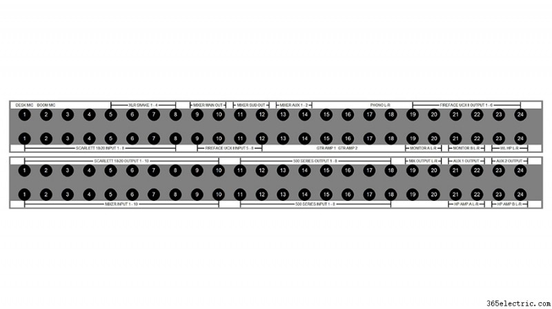
There are lots of uses for each of these modes and the possibilities are endless, but here are some examples of how I have set up my patchbay to meet the needs of the various devices in my studio.

The top left corner of my patchbay is where my microphones come in. Some of my microphones (like this boom mic) are directly wired into the top row of jacks on the back of my patchbay. Alternatively, I could have an XLR panel in the back of the room that connects to the top row of jacks on the back of the patchbay. That way, I could connect a microphone to that XLR panel which would then be available on the top row of my patchbay.
I will almost always want my microphones to connect to the microphone preamps on my audio interface, so I’ve set these jacks up in full-normal mode. This means the mics will be connected to my interface by default without any patching. But if I want to patch the microphone to a different mic preamp I can simply do so with a patch cable.
I chose to use full-normal instead of half-normal, because I don’t want to accidentally connect my microphone to two preamps that are both supplying phantom power. When I connect a patch cable to the top jack, it automatically breaks the connection to my interface. This also prevents me from connecting two microphones to the same audio interface preamp.
The other essential connections for my typical workflow are set up using half-normal mode. For example, my interface outputs flow directly to the input of my monitors. If I want to patch my turntable directly into my monitors for a pure analog connection, I can patch from my phono output jacks to the monitor input jacks and bypass the other components of the system. Given that this is set up in half-normal mode, the default connection from the interface outputs will be broken when I connect to the monitor input jacks.
Half-normal jacks also provide a way to split a signal. Let’s say I want to send my interface output to the input of my monitors while also sending that output to my wireless headphones. I just patch the output of my interface to the input of my wireless headphone transmitter and the signal still flows down to the speakers, because nothing is connected to the bottom jack. Remember – in half-normal mode, the connection is only broken when there is a plug in the bottom jack.
I use ‘Thru’ mode for my outboard effects and preamps because I don’t want the outputs of my compressor or outboard preamps to feed into their own inputs and create a feedback loop. Setting these modules to ‘Thru’ mode keeps the top jack and bottom jack independent from one another, meaning I need to manually patch these devices anytime I want to use them.
Which Patchbay Should You Use?
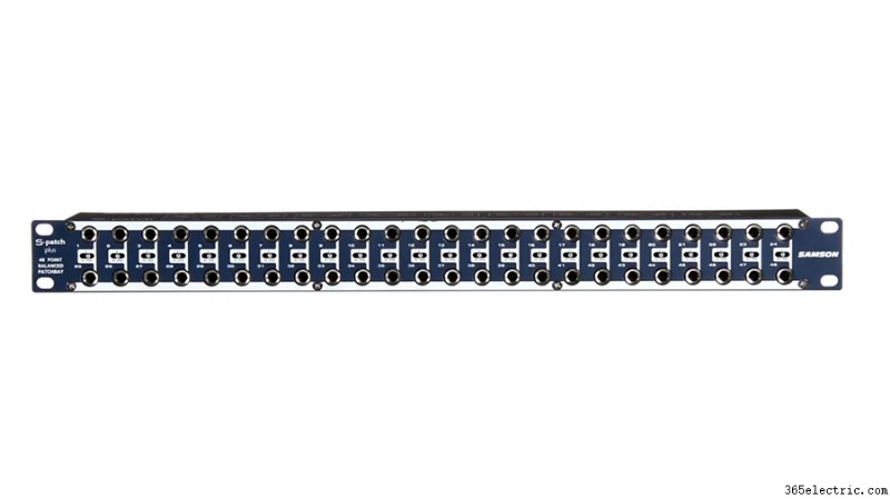
I have two 48-point ¼-inch TRS patchbays. One is a Neutrik, which costs about $100. The other is a Samson S-Patch Plus, which is a little more expensive. I’ve had some time to compare these two options and I think the Samson is well worth the extra money.
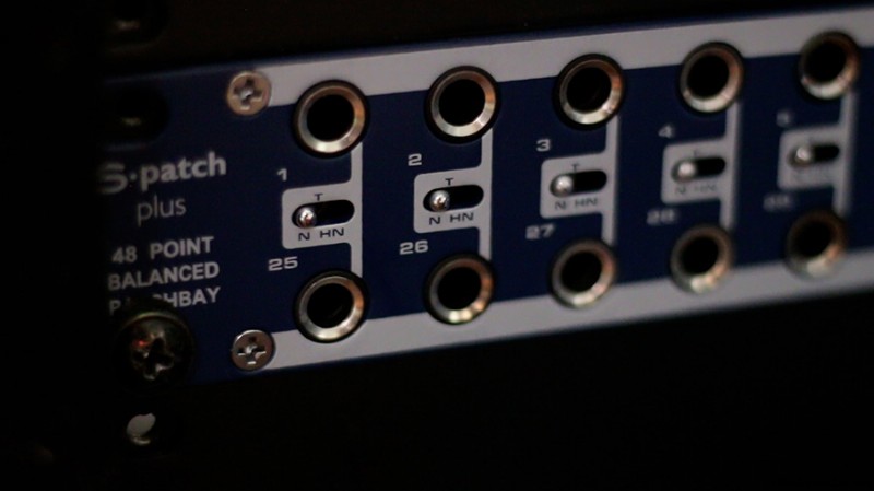
If I want to change the mode on any module in the Samson S-Patch Plus, I just need to toggle the switch between the top and bottom jack.

In order to switch the mode on one of the Neutrik modules, I need to disconnect the jacks from the front and back, remove the front panel of the entire patchbay, take the module out, flip it around, and reassemble everything.
This has caused me a few headaches as I have continued to add components and shift things around on the patchbays, so I would definitely recommend going with the Samson S-Patch Plus if you’re on the fence.
You should also consider how much space you have and how many connections you’ll need. These two 48-port patchbays take up 1RU of rack space each, which can really add up…
If you’ve got a larger collection of components or less rack space to work with, you may want to look into a TT (or tiny telephone connector) patchbay instead. These will be more space efficient, as the density of connection points is much greater with these smaller connectors.
You will also find patchbays that have multi-channel connectors in the rear rather than the same connection type on front and back. This can make for a cleaner setup, utilizing multi-channel fanouts rather than an individual cable on the rear panel for each connection.
